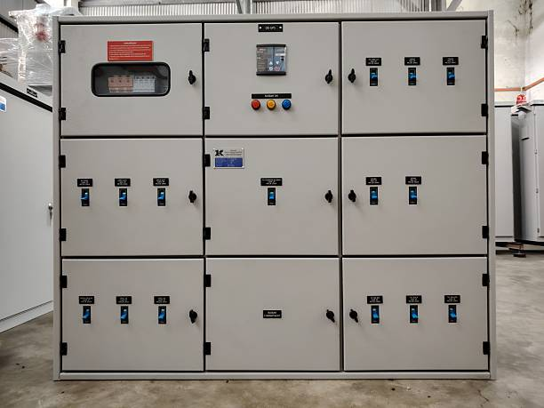
Metal enclosed switchgear assemblies are essential components of electrical distribution infrastructure, providing a controlled environment for switching devices, busbars, protection equipment, and associated connections. Their long-term performance depends not only on equipment quality but also on how carefully the assemblies are transported, installed, aligned, connected, and commissioned.
In industrial plants, commercial buildings, utility substations, and infrastructure projects, installation errors can create persistent problems. Misaligned enclosures may complicate busbar connections, moisture can degrade insulation, and poorly prepared foundations can introduce mechanical stress. Even when equipment meets its specified electrical ratings, inadequate installation practices can compromise operational reliability and service life.
A durable metal enclosed switchgear installation begins with detailed site planning and continues through environmental protection, cable termination, grounding, testing, and preventive maintenance. Understanding these considerations helps project engineers, electrical contractors, and facility managers establish installations that remain safe, accessible, and dependable throughout their intended operating life.
Understanding Metal Enclosed Switchgear Assemblies
Metal enclosed switchgear consists of electrical switching and control equipment housed within grounded metal enclosures. Depending on the design and voltage class, an assembly may contain circuit breakers, load-break switches, busbars, instrument transformers, protective relays, cable compartments, and control wiring.
The metal enclosure provides a defined physical barrier around electrical components and supports the intended equipment configuration. However, enclosure construction alone does not guarantee safety or durability. Performance depends on the complete assembly, its installation conditions, and compliance with the manufacturer’s specified requirements.
Differences Between Indoor and Outdoor Installations
Indoor switchgear is generally installed in dedicated electrical rooms or substations where temperature, moisture, ventilation, and access can be managed through the building design. The installation must accommodate working clearances, cable entry arrangements, room ventilation, and safe maintenance access.
Outdoor switchgear faces additional environmental demands, including rain, wind-driven dust, solar heating, humidity, and potentially corrosive atmospheres. Its installation may require weather-resistant enclosures, properly sealed joints, drainage provisions, and suitable foundation arrangements.
The equipment’s specified enclosure rating and environmental limits should guide site preparation. An outdoor-rated assembly should not be assumed suitable for every exposure condition without checking the manufacturer’s documentation.
Why Installation Quality Determines Service Life
Switchgear assemblies contain carefully aligned mechanical components and electrical connections. Improper handling or uneven support can affect enclosure alignment, door operation, interlocks, and connections between adjoining sections.
Installation quality also influences insulation condition, grounding continuity, thermal performance, and maintenance accessibility. Addressing these requirements before energization is generally more effective than correcting installation defects after the system enters service.
Site Assessment and Foundation Preparation
Foundation preparation is one of the first major steps in installing durable metal enclosed switchgear assemblies. The supporting structure must accommodate the equipment’s weight, anchoring requirements, cable entry points, and any applicable seismic or mechanical loading.
Verifying Floor Strength and Levelness
Before delivery, the installation team should confirm that the concrete foundation, structural steelwork, or finished floor meets the approved equipment drawings. The support must withstand the installed load without unacceptable movement or deformation.
The foundation surface should be checked for levelness, flatness, and readiness for installation. Uneven support can cause adjacent sections to sit at different heights, making it difficult to join enclosure frames and align busbar connections.
Where the design requires embedded channels, mounting plates, or anchor bolts, their locations should be verified against the manufacturer’s dimensional drawings before the switchgear arrives.
Confirming Cable Trenches and Conduit Locations
Cable trenches and conduits must align with the switchgear’s designated entry openings. Incorrect positioning can force cables into tight bends, create congestion below the enclosure, or interfere with grounding conductors and control wiring.
Engineers should coordinate the foundation plan with power cable sizes, termination arrangements, control cable routes, and future maintenance needs. Trenches should also have appropriate covers, drainage provisions, and protection against water accumulation where required by the project design.
Planning Anchorage and Seismic Requirements
The switchgear must be secured using the anchoring arrangement specified for the actual equipment and installation conditions. Anchor type, location, embedment, and tightening requirements should follow approved engineering drawings and manufacturer instructions.
Where seismic requirements apply, the equipment and its anchorage must be assessed as a coordinated installation. Standard anchoring details should not be substituted for a project-specific seismic design when additional qualification is required.
Safe Transportation, Handling, and Storage
Switchgear can be damaged before installation if shipping, lifting, or storage procedures are not followed. Enclosure distortion, damaged insulators, displaced components, and moisture contamination may not always be immediately visible.
Inspecting Equipment on Delivery
The receiving team should compare delivered equipment against the shipping documents and approved equipment schedule. Enclosures, doors, lifting points, protective covers, and visible accessories should be inspected for signs of impact or deformation.
Any damage, missing parts, or irregularities should be documented and reported before installation proceeds. The team should also review the equipment-specific lifting instructions and identify the approved lifting points.
Using Correct Lifting and Handling Methods
Each shipping section should be moved using the lifting method and equipment specified by the manufacturer. Improvised lifting points, unsuitable sling arrangements, or excessive mechanical force can damage the enclosure and its internal components.
The handling plan should account for equipment weight, center of gravity, access restrictions, overhead obstructions, and the capacity of lifting equipment. Shipping braces and temporary supports must remain in place until the relevant installation instructions permit their removal.
Protecting Switchgear During Storage
If installation cannot begin immediately, the equipment should be stored in a location that meets the manufacturer’s environmental requirements. Protection against moisture, dust, condensation, and accidental impact is especially important.
Protective packaging should be managed according to the storage instructions rather than removed indiscriminately. Where space heaters or other moisture-control measures are specified, their use should be monitored and documented.
Storage inspections should continue until the assembly is ready for installation. Prolonged exposure to unsuitable conditions may require additional inspection or testing before commissioning.
Alignment and Assembly of Switchgear Sections
Many metal enclosed switchgear lineups are delivered in multiple shipping sections that must be joined at the installation site. Accurate positioning is essential for maintaining the intended mechanical and electrical configuration.
Positioning and Leveling Each Section
The installation team should follow the approved general arrangement and assembly drawings to establish the correct sequence of sections. Each section must be positioned, leveled, and aligned according to the manufacturer’s specified tolerances.
Where shimming is permitted, suitable materials and procedures should be used to achieve the required alignment without compromising the support arrangement. Sections should not be forced together to compensate for a poorly prepared foundation.
Manufacturer installation guidance emphasizes aligning and leveling shipping sections before completing their mechanical connections.
Joining Enclosures and Busbar Connections
Once the sections are correctly positioned, the team can complete the specified mechanical joints and electrical connections. Bolts, gaskets, joining hardware, and connection components should be installed according to the approved instructions.
Busbar connections deserve particular attention because alignment errors, contaminated contact surfaces, or incorrect tightening can contribute to overheating and premature failure. Specified contact preparation methods and torque values must be followed; assumptions based on similar equipment should not replace the applicable instructions.
After assembly, technicians should verify enclosure alignment, door movement, mechanical interlocks, and the condition of accessible connection points before proceeding to final testing.
Environmental Control and Ventilation
Temperature and moisture management are important for preserving insulation condition and reducing corrosion inside switchgear enclosures. Even a well-designed assembly can deteriorate prematurely when installed in an unsuitable environment.
Managing Heat and Airflow
Electrical components generate heat during operation, with the amount depending on current loading, contact resistance, equipment design, and ambient temperature. The installation should preserve the ventilation paths and clearances specified by the manufacturer.
Electrical rooms may require mechanical ventilation or temperature control where heat loads or local environmental conditions demand it. Ventilation openings must not be blocked by construction materials, stored items, or nearby equipment.
Outdoor installations should also be assessed for direct solar exposure and the potential for elevated internal temperatures. Any proposed shading or enclosure modification must remain compatible with the equipment’s tested design and warranty requirements.
Preventing Moisture and Condensation
Moisture can reduce insulation performance, encourage corrosion, and contribute to tracking across contaminated insulating surfaces. Risk factors include high humidity, temperature fluctuations, water ingress, and inadequate storage conditions.
Installation planning should address roof and wall leakage, door seals, cable-entry sealing, drainage, and condensation control. Anti-condensation heaters or other moisture-management devices should be installed and operated where specified.
After exposure to water or suspected moisture contamination, the assembly should not simply be energized after its exterior appears dry. A qualified assessment must determine whether cleaning, drying, inspection, or electrical testing is necessary.
Controlling Dust and Corrosive Contaminants
Industrial environments may contain cement dust, conductive particles, chemical vapors, salt-laden air, or other contaminants. These substances can damage finishes, obstruct ventilation, and affect insulation or contact performance.
The installation location should match the environmental classification of the selected equipment. Where special protection is required, it should be incorporated into the original design rather than improvised through unapproved modifications.
Electrical Connections, Earthing, and Cable Termination
Electrical installation work must preserve the equipment’s designed current-carrying capability, insulation clearances, and fault-current withstand characteristics.
Cable Routing and Termination
Power cables should enter the designated compartments and follow the minimum bending radii specified by the cable and termination manufacturers. Excessive bending or mechanical strain can damage insulation and place unwanted force on terminals.
Terminations should be compatible with the conductor material, cable size, insulation system, and equipment terminal design. Correct crimping tools, lugs, stress-control components, and installation methods should be used where applicable.
Before energization, technicians should verify phase identification, termination tightness, cable support, and clearance from adjacent live parts. Cable arrangements should also allow future inspection and replacement without disturbing unrelated connections unnecessarily.
Earthing and Bonding Integrity
The metal enclosure must be connected to the installation’s protective earthing system in accordance with the approved design. Earthing conductors, bonding links, and joints should be installed with the specified materials and connection methods.
Grounding continuity is critical because accessible metal parts may need to carry fault current until protective devices disconnect the supply. The complete earthing arrangement must therefore be designed to meet the applicable fault-current and disconnection requirements.
Before energization, the team should verify protective bonding and inspect the relevant connections. A properly connected enclosure does not eliminate the need for a correctly designed site earthing system.
Commissioning, Testing, and Documentation
Commissioning confirms that the installed switchgear matches the approved design and is ready for controlled operation. The required tests depend on the equipment type, voltage class, applicable standards, and manufacturer’s instructions.
Mechanical and Electrical Verification
Pre-commissioning inspections should cover enclosure assembly, hardware, cable terminations, labels, interlocks, protective earthing, and the condition of accessible insulating components.
Electrical testing may include insulation resistance measurements, contact resistance measurements where applicable, verification of control wiring, and checks of instrument transformer circuits. Protective relays and circuit breakers should be tested according to the approved commissioning plan.
Test values must be interpreted against the applicable equipment requirements and test conditions. No single test result should be treated as proof that every part of the installation is satisfactory.
Functional Testing and Controlled Energization
Functional testing verifies that switching devices, electrical interlocks, trip circuits, alarms, and control systems operate as intended. Protection settings should be checked against the approved coordination study before the system is placed in service.
Energization should proceed only after required inspections, testing, defect resolution, and formal authorization are complete. The responsible team should follow the site’s switching procedures and establish clear communication between commissioning personnel and the system operator.
Maintaining Installation Records
The final documentation package should include approved drawings, equipment identification details, installation inspection records, test results, protection settings, and any approved deviations from the original design.
These records provide a reliable reference for maintenance, troubleshooting, future modifications, and compliance reviews. Accurate documentation also helps distinguish original installation conditions from changes introduced during later work.
Long-Term Maintenance for Durable Performance
Durability depends on the continued condition of mechanical assemblies, electrical connections, insulation systems, and environmental protection measures. A maintenance program should reflect equipment criticality, operating conditions, manufacturer recommendations, and the consequences of failure.
Routine Inspection and Condition Assessment
Inspections may include checking for corrosion, damaged seals, unusual odors, contamination, abnormal noise, signs of overheating, and deterioration of visible components. Thermal inspections can help identify unusual temperature patterns at accessible connections when conducted under suitable operating conditions.
Internal inspection and maintenance must follow approved isolation, lockout, verification of absence of voltage, and earthing procedures as applicable. Equipment should never be opened or serviced on the assumption that an indication alone confirms it is safe.
Managing Changes and Upgrades
Adding feeders, changing connected loads, modifying protection settings, or relocating equipment can affect the electrical and mechanical integrity of the original installation.
Before making changes, engineers should review fault levels, busbar ratings, enclosure compatibility, cable capacity, protection coordination, and available space. Any modification must preserve the assembly’s intended safety and performance characteristics.
A structured maintenance and change-management process helps extend service life while reducing the risk that small installation defects develop into expensive operational problems.
Conclusion
Installing durable metal enclosed switchgear assemblies requires a coordinated approach that combines civil preparation, careful equipment handling, precise mechanical assembly, environmental control, and thorough electrical verification. Each stage influences the reliability of the finished installation, from the stability of the foundation to the integrity of busbar connections and protective earthing.
At Meta Power Solutions, we emphasize the importance of accurate installation drawings, manufacturer-approved assembly procedures, suitable environmental conditions, and verified cable termination practices. Comprehensive commissioning and well-maintained technical documentation provide additional assurance that the equipment is ready for safe and reliable operation.
Long-term durability also depends on routine inspections and disciplined change management. By addressing installation risks before energization and maintaining the assembly according to its operating requirements, facility owners can reduce avoidable failures, simplify maintenance, and protect the performance of critical electrical infrastructure throughout its intended service life.